
Band-IT Dragster Assembly Instructions
The Band-IT is a rubber band powered dragster with 3D printed components. Print one and take it for a spin. Better yet, print two and race against each other. Endless hours of fun are waiting to be discovered.
The Band-IT component parts may be downloaded and printed at Band-IT Dragster. Follow these instructions to learn how to assemble your dragster once all the components are printed.
Band-IT
The Band-IT consists of 17 total components: 16 that are printed and a rubber band (approximate 6 inches / 16mm in length) that may be purchased separately (see Figure 1). Five of the components will be duplicated and several of the components may be fabricated together in one print.
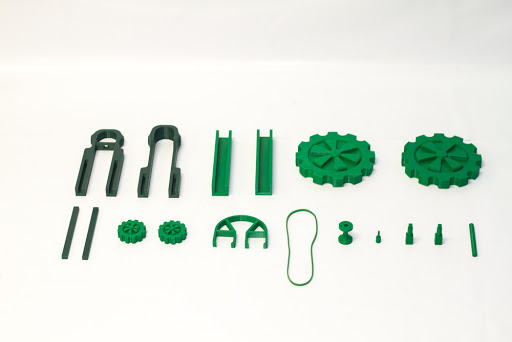
Figure 1
Figure 2 shows the components that will need to be printed separately as one batch. These should be printed with 90-100% infill since they will be subjected to the most stress. Otherwise, the rest of the components may be printed using a standard infill.
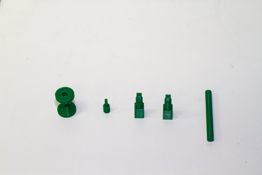
Figure 2
As a note before assembly, joining components should not need any adhesive since the parts were designed to have a good amount of tension once joined. However, one may want to place adhesive in the joints where components may come under some stress, e.g. between axles and wheels and along the frame of the dragster. This option is left up to the discretion of the fabricator. The following are a list of steps in assembling the dragster.
Step 1: Insert the rubber band pin into the rear axle (Figures 3 and 4).
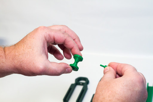
Figure 3

Figure 4
Step 2: Insert the rear axle pin into the large wheel (Figures 5 and 6). This should be done for each large wheel.
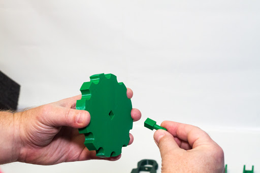
Figure 5
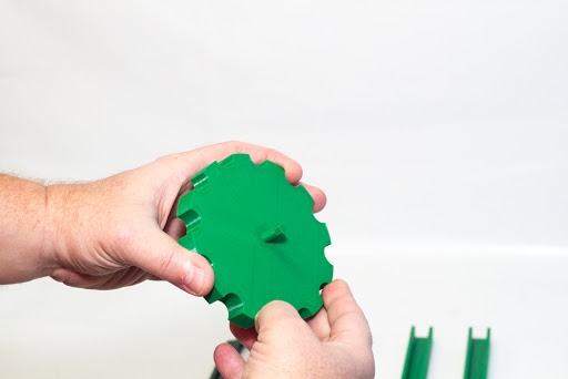
Figure 6
Step 3: Secure the rubber band to the front section of the dragster frame (Figures 7 and 8). The rubber band should be looped through the hole in the cross bar of the frame and pulled taut.
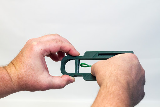
Figure 7
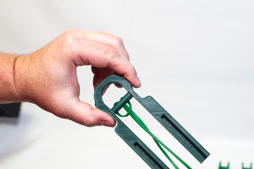
Figure 8
Step 4: Align the front of the frame with the rear frame component in preparation for the frame joiner component insertion (Figure 9).
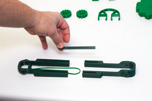
Figure 9
Step 5: Place both frame joiners into the slots on the front and rear frames (Figure 10). This joiner aids in keeping the full frame together.
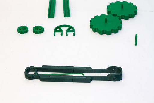
Figure 10
Step 6: Place the two u-shaped body connectors on the top part of each leg of the frame assembly (Figures 11, 12, 13 and 14). These components aid in keeping the frame stiff and simulates the bottom part of dragster body components to be designed in the future.
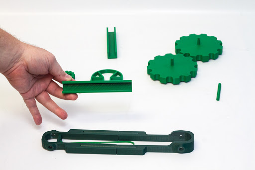
Figure 11
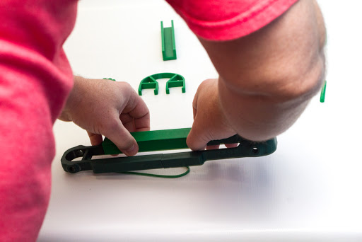
Figure 12
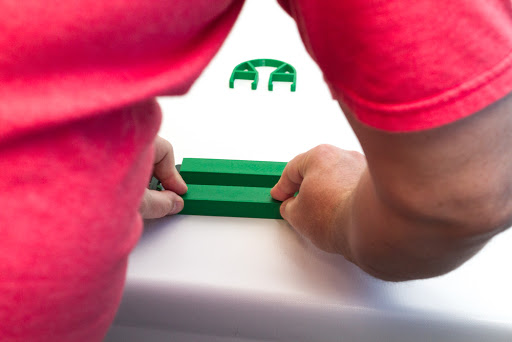
Figure 13
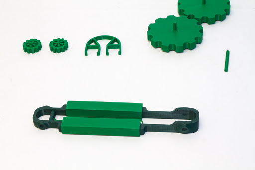
Figure 14
Step 7: Take the front axle and place it in the hole on one small wheel (Figures 15 and 16).
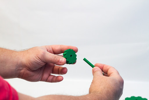
Figure 15
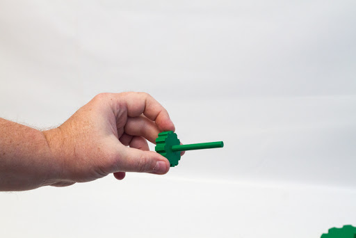
Figure 16
Step 8: Place the one small wheel and axle assembly through the holes in the front of the frame (Figure 17).
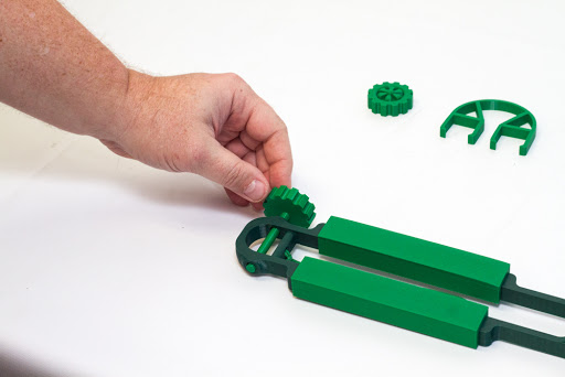
Figure 17
Step 9: Take the remaining small wheel and attach it to the front axle that has been inserted into the frame (Figures 18 and 19).
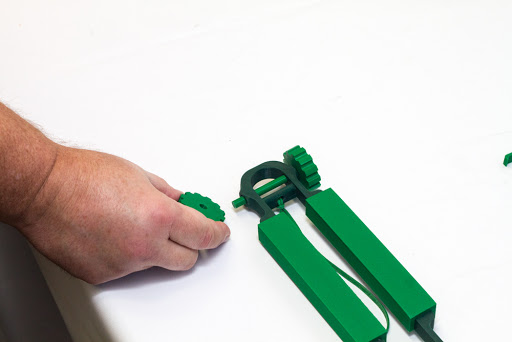
Figure 18
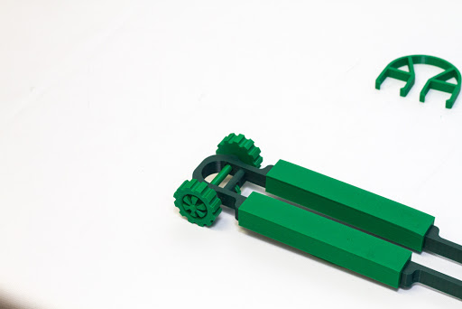
Figure 19
Step 10: Place the rear axle assembly in the rear of the frame assembly between the holes in the rear of the frame (Figure 20). This will be in preparation for attachment of the two large wheel assemblies.
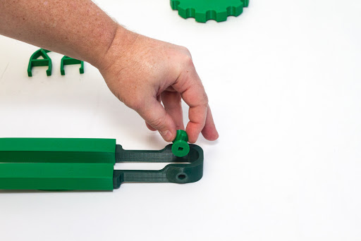
Figure 20
Step 11: Attach each rear wheel assembly into the square holes on each end of the rear axle (Figures 21, 22, 23 and 24).
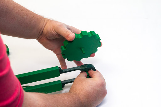
Figure 21
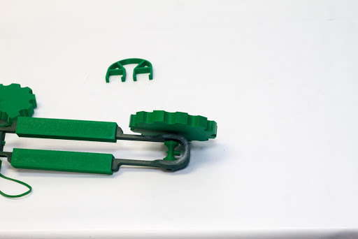
Figure 22
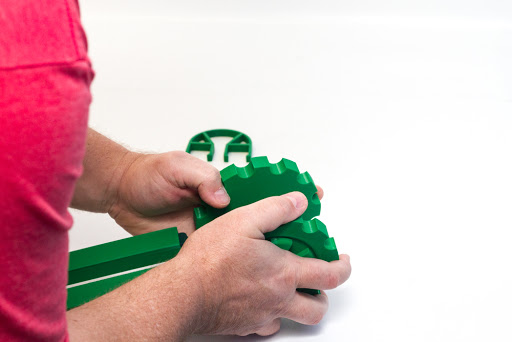
Figure 23
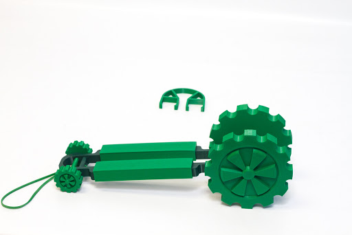
Figure 24
Step 12: Place the rubber band backlash guard on to the dragster frame (Figures 25 and 26).
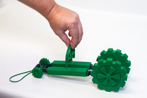
Figure 25
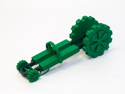
Figure 26
The Band-it Dragster is now completely assembled. To provide propulsion for the dragster, place the rubber band on the pin of the rear axle (Figures 27 and 28). Rotate the rear wheel assembly to coil the rubber band around the rear axle. Now you are free to let it go and see how far the dragster can travel.
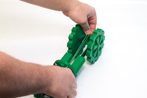
Figure 27
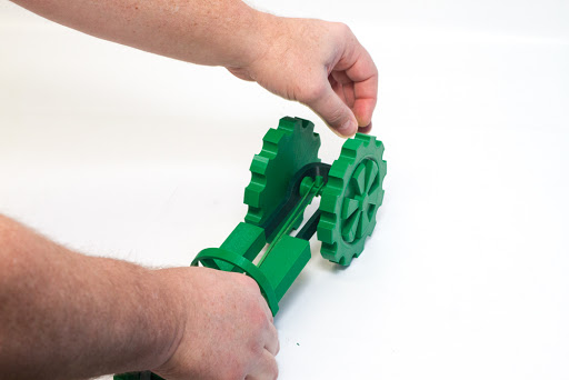
Figure 28